
1. Introduction
- CAN stands for Controller Area Network (CAN bus). This protocol is very popular in automotive domain. In order to understand more about history, benefits, characteristics, message format of CAN, you can refer:
http://www.ni.com/white-paper/2732/en/
http://www.ti.com/lit/an/sloa101b/sloa101b.pdf
- As you knew in Introduction to ESP32, ESP32 also supports CAN interface. So I am going to make a demo for this with Arduino.
- In this demo, 2 ESP32 modules will be used: first module will send the string "hellocan" to second module. The second module will convert the string to upper case and respond it back to first module and first module will show the result in theTerminal.
2. Hardware
- ESP32 only supplies CAN controller. So you need CAN transceiver for this demo. I bought 2 CAN trasceivers here.

- ESP32 GPIO4 will act as CAN_Rx.
- So you can connect pins belows (ESP32_X: module ESP32 X, CAN_X: module CAN X, where X is 1 or 2 since we have 2 modules):
ESP32_1 IO5 - CAN_1 CTX
ESP32_1 IO4 - CAN_1 CRX
CAN_1 CANH - CAN_2 CANH
CAN_1 CANL - CAN_2 CANL
ESP32_2 IO5 - CAN_2 CTX
ESP32_2 IO4 - CAN_2 CRX
3. Software
- In order to make this demo, I used CAN driver which is made by Thomas Barth (Thanks Thomas :))
- Download the CAN library for ESP32 here. Unzip it and copy to "Arduino/libraries" folder.
- Source code for first ESP32 module: receiving string, converting to upper case and respond back:
- Source code for second ESP32 module: sending the string that need to be converted to upper case, receiving response and show it to Terminal
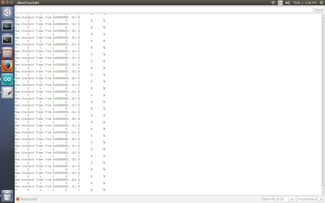
4. Result
- CAN stands for Controller Area Network (CAN bus). This protocol is very popular in automotive domain. In order to understand more about history, benefits, characteristics, message format of CAN, you can refer:
http://www.ni.com/white-paper/2732/en/
http://www.ti.com/lit/an/sloa101b/sloa101b.pdf
- As you knew in Introduction to ESP32, ESP32 also supports CAN interface. So I am going to make a demo for this with Arduino.
- In this demo, 2 ESP32 modules will be used: first module will send the string "hellocan" to second module. The second module will convert the string to upper case and respond it back to first module and first module will show the result in theTerminal.
2. Hardware
- ESP32 only supplies CAN controller. So you need CAN transceiver for this demo. I bought 2 CAN trasceivers here.
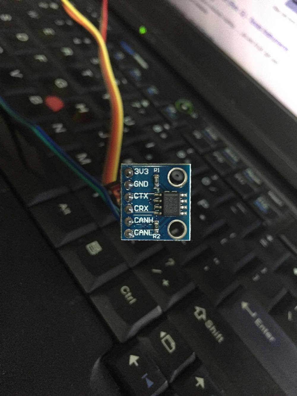
Figure: ESP32 CAn transceiver
- ESP32 GPIO5 will act as CAN_Tx.- ESP32 GPIO4 will act as CAN_Rx.
- So you can connect pins belows (ESP32_X: module ESP32 X, CAN_X: module CAN X, where X is 1 or 2 since we have 2 modules):
ESP32_1 IO5 - CAN_1 CTX
ESP32_1 IO4 - CAN_1 CRX
CAN_1 CANH - CAN_2 CANH
CAN_1 CANL - CAN_2 CANL
ESP32_2 IO5 - CAN_2 CTX
ESP32_2 IO4 - CAN_2 CRX
3. Software
- In order to make this demo, I used CAN driver which is made by Thomas Barth (Thanks Thomas :))
- Download the CAN library for ESP32 here. Unzip it and copy to "Arduino/libraries" folder.
- Source code for first ESP32 module: receiving string, converting to upper case and respond back:
1 2 3 4 5 6 7 8 9 10 11 12 13 14 15 16 17 18 19 20 21 22 23 24 25 26 27 28 29 30 31 32 33 34 35 36 37 38 39 40 41 42 43 44 45 | #include <ESP32CAN.h> #include <CAN_config.h> /* the variable name CAN_cfg is fixed, do not change */ CAN_device_t CAN_cfg; void setup() { Serial.begin(115200); Serial.println("iotsharing.com CAN demo"); /* set CAN pins and baudrate */ CAN_cfg.speed=CAN_SPEED_1000KBPS; CAN_cfg.tx_pin_id = GPIO_NUM_5; CAN_cfg.rx_pin_id = GPIO_NUM_4; /* create a queue for CAN receiving */ CAN_cfg.rx_queue = xQueueCreate(10,sizeof(CAN_frame_t)); //initialize CAN Module ESP32Can.CANInit(); } void loop() { CAN_frame_t rx_frame; //receive next CAN frame from queue if(xQueueReceive(CAN_cfg.rx_queue,&rx_frame, 3*portTICK_PERIOD_MS)==pdTRUE){ //do stuff! if(rx_frame.FIR.B.FF==CAN_frame_std) printf("New standard frame"); else printf("New extended frame"); if(rx_frame.FIR.B.RTR==CAN_RTR) printf(" RTR from 0x%08x, DLC %d\r\n",rx_frame.MsgID, rx_frame.FIR.B.DLC); else{ printf(" from 0x%08x, DLC %d\n",rx_frame.MsgID, rx_frame.FIR.B.DLC); /* convert to upper case and respond to sender */ for(int i = 0; i < 8; i++){ if(rx_frame.data.u8[i] >= 'a' && rx_frame.data.u8[i] <= 'z'){ rx_frame.data.u8[i] = rx_frame.data.u8[i] - 32; } } } //respond to sender ESP32Can.CANWriteFrame(&rx_frame); } } |
1 2 3 4 5 6 7 8 9 10 11 12 13 14 15 16 17 18 19 20 21 22 23 24 25 26 27 28 29 30 31 32 33 34 35 36 37 38 39 40 41 42 43 44 45 46 47 48 49 50 51 52 53 54 55 56 57 58 | #include <ESP32CAN.h> #include <CAN_config.h> /* the variable name CAN_cfg is fixed, do not change */ CAN_device_t CAN_cfg; void setup() { Serial.begin(115200); Serial.println("iotsharing.com CAN demo"); /* set CAN pins and baudrate */ CAN_cfg.speed=CAN_SPEED_1000KBPS; CAN_cfg.tx_pin_id = GPIO_NUM_5; CAN_cfg.rx_pin_id = GPIO_NUM_4; /* create a queue for CAN receiving */ CAN_cfg.rx_queue = xQueueCreate(10,sizeof(CAN_frame_t)); //initialize CAN Module ESP32Can.CANInit(); } void loop() { CAN_frame_t rx_frame; //receive next CAN frame from queue if(xQueueReceive(CAN_cfg.rx_queue,&rx_frame, 3*portTICK_PERIOD_MS)==pdTRUE){ //do stuff! if(rx_frame.FIR.B.FF==CAN_frame_std) printf("New standard frame"); else printf("New extended frame"); if(rx_frame.FIR.B.RTR==CAN_RTR) printf(" RTR from 0x%08x, DLC %d\r\n",rx_frame.MsgID, rx_frame.FIR.B.DLC); else{ printf(" from 0x%08x, DLC %d\n",rx_frame.MsgID, rx_frame.FIR.B.DLC); for(int i = 0; i < 8; i++){ printf("%c\t", (char)rx_frame.data.u8[i]); } printf("\n"); } } else { rx_frame.FIR.B.FF = CAN_frame_std; rx_frame.MsgID = 1; rx_frame.FIR.B.DLC = 8; rx_frame.data.u8[0] = 'h'; rx_frame.data.u8[1] = 'e'; rx_frame.data.u8[2] = 'l'; rx_frame.data.u8[3] = 'l'; rx_frame.data.u8[4] = 'o'; rx_frame.data.u8[5] = 'c'; rx_frame.data.u8[6] = 'a'; rx_frame.data.u8[7] = 'n'; ESP32Can.CANWriteFrame(&rx_frame); } } |
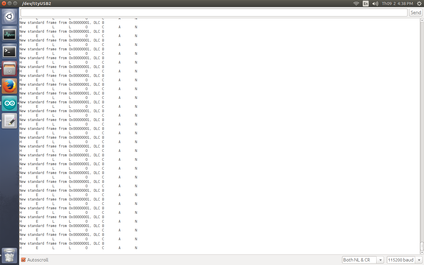
Figure: ESP32 CAN demo


26 comments:
ESP32 Software Serial library or exampale please.
esp32 has 3 serial interfaces so you need not SoftSerial.
here is it:
Demo 2: How to use multiple Serial ports on Arduino ESP32
http://www.iotsharing.com/2017/05/how-to-use-serial-arduino-esp32-print-debug.html
Can you test it using MCP2551 ?
Sorry I do not have MCP2551 :(
can I use different esp32 pins for can tx/rx ? or they must be gpio5 gpio4
Hi
Proposed connection:
ESP32 VP231 Description
GPIO5 / GPIO12 / GPIO25 D CAN TX
GPIO4 / GPIO14 / GPIO35 R CAN RX
It work with MCP2551 to, but use 5V for supply not 3.3 V.
I was wondering how code would look like if I wanted to send 3 messages, each with different ID in one go. I was trying to do 3x the same code ending with ESP32Can.CANWriteFrame(&rx_frame); but it seems only one first ID is being sent not the following 2 with different IDs.
Can you please explain what's the difference between the CAN driver and the Arduino library and where you use each one of them ?
what do i need yo change to read data from car CAN BUS ?
Hi it used: xQueueReceive to receive data
can you explain all the parameters in
(xQueueReceive(CAN_cfg.rx_queue,&rx_frame, 3*portTICK_PERIOD_MS)==pdTRUE) ?
Just tested with both ESP32 it's works. But using Logic Analyzer, it's unreadable. It's looks has wrong speed
Hello, tested with ESP32 + SN65HVD230 module. It wasn't worked for my Astra H because the middle speed bus in GM models uses an unusual 95kbps speed. However I could figure out, in ESP32SJA1000.cpp this snipped can be added in begin() at the section "switch (baudRate)":
case (long)95E3:
modifyRegister(REG_BTR1, 0x0f, 0x0c);
modifyRegister(REG_BTR0, 0x3f, 25);
break;
Now this works.
sixweb
Hello guys,
I flashed the ESP32 with the example code provided. However, it is not working. Nothing outs from the GPIO5 and GPIO4 pins. The library is not working.
Has someone successfully made it worked?
How to use cjmcu 1051 instead of the cjmcu 230. I cant get it to work with the same wiring schematic.
Thank you.
Got it to work with cjmcu 1051. Just have set the s pin in the transceiver low or ground. Preferably low.
Thank you.
Hey there,
I followed your step. it works. If I plug the Can bus line to real Vehicle. I cannot receive any data. Does the code work for real vehicle
I Don't get it working. I conected the ESP32(DOIT DEVKITV1) to SN65HVD230 by GPIO5 to CTX and GPIO4 to CRX. I downloaded the Library as ZIP and loaded it into Arduino by ZIP-Bibliothek hinzufügen. I uploaded to the first ESP32 the ESP32CAN example and to the second ESP32 the ESP32CANSEND example. But i dont get only feedback in the serial monitor with this message:
ets Jun 8 2016 00:22:57
rst:0x1 (POWERON_RESET),boot:0x17 (SPI_FAST_FLASH_BOOT)
configsip: 0, SPIWP:0xee
clk_drv:0x00,q_drv:0x00,d_drv:0x00,cs0_drv:0x00,hd_drv:0x00,wp_drv:0x00
mode:DIO, clock div:1
load:0x3fff0018,len:4
load:0x3fff001c,len:808
load:0x40078000,len:6084
load:0x40080000,len:6696
entry 0x400802e4
E (106) spiram: SPI RAM enabled but initialization failed. Bailing out.
iotsharing.com CAN demo
No things are written like "HELLOCAN".
What is the problem, what did I wrong?
I am having trouble tranmitting the CAN frame using ESP32 with cjmcu-1051 board (PIN S is grounded) .Is there a way to know the if there is a TX error or Tx err que status ? Do i need to terminate both ends using 120 Ohm ?It is rather a very short CAN wire your example didnt talk about terminations .So i assume may be this is not requied.Any helpis appreciated
Hi there,
I am only having the first CAN message. Where's the rest?
ID: 0x80 DLC: 0 Data: 0x00 0x00 0x00 0x00 0x00 0x00 0x00 0x00
ID: 0x80 DLC: 0 Data: 0x00 0x00 0x00 0x00 0x00 0x00 0x00 0x00
ID: 0x80 DLC: 0 Data: 0x00 0x00 0x00 0x00 0x00 0x00 0x00 0x00
...
Should be like:
" 80";"0";"";""
"286";"8";"00 00 00 00 12 00 FE FF"
"339";"8";"00 00 00 00 00 00 9A 03"
"173";"8";"D4 7D 2A 01 25 02 24 00"
"156";"7";"FD 05 21 00 00 00 00"
"279";"8";"00 00 00 00 00 00 00 00"
" 80";"0";"";""
"286";"8";"00 00 00 00 FC FF F8 FF"
"339";"8";"00 00 00 00 00 00 9A 03"
"173";"8";"D4 7D 2A 01 25 02 24 00"
"156";"7";"FD 05 21 00 00 00 00"
"279";"8";"00 00 00 00 00 00 00 00"
Here is the simple code:
void loop() {
CAN_frame_t rx_frame;
if(xQueueReceive(CAN_cfg.rx_queue, &rx_frame, 3*portTICK_PERIOD_MS) == pdTRUE){
sprintf(msgString, "ID: 0x%.2X DLC: %1d Data: ", rx_frame.MsgID, rx_frame.FIR.B.DLC);
Serial.print(msgString);
for(int i = 0; i < 8; i++){
sprintf(dataString, "0x%.2X ", rx_frame.data.u8[i]);
Serial.print(dataString);
}
Serial.println();
}
}
Any ideas?
I wish there were a way to do this in MicroPython, but only the PyBoard version seems to have a CAN class. Unsupported on ESP32... [sadface]
is it possible to use 2 can lines at same time? I need to receive from 2 separate lines
Thanks, it works fine for me! (with SN65HVD230 CAN Board + ESP32 DOIT layout board).
The resistance across the wires was 60Ω.
Which CAN Transceiver are you using?
Post a Comment